CS/EE 5710/6710 Digital VLSI DesignCAD Assignment #7 Group Mini-ProjectVideo Pattern Generator Due Friday October 28th, 5:00pm Overview: In this assignment,
your group will design a video pattern generator capable of driving a VGA style
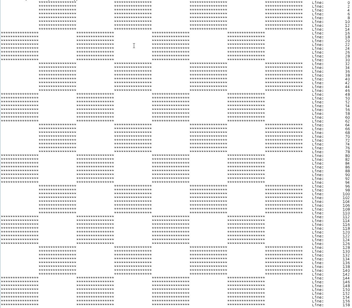
monitor.� You may choose to create either
a checkerboard
or a pattern with a text
message in it.� Groups that
successfully create a text message (choose your own message!) will receive a 5
semester point bonus.
You will design the generator in modules, a horizontal
module, a vertical module and a top level module where you will bring
everything together. Each module will use a different design style and tool
set. You will use your group�s standard cell library for all of the modules.
Horizontal module: Construct the horizontal module using Verilog according to
these specifications.� After you have confirmed that your module
meets the specifications, follow use the procedure you have learned in the class to:
1.
Convert your behavioral Verilog file into structural Verilog
using syn-dc and your library.�
2.
Convert your structural Verilog into layout using the cad-soc.
3.
Create a schematic by importing your structural Verilog into Cadence as a schematic
4.
Perform LVS on the imported Verilog and the SOC layout.�
5.
Confirm that the schematic you imported from the structural Verilog
meets the same specifications as your original behavioral Verilog.
Vertical module: Construct the vertical module in the same way according to these specifications.�
Top module: Construct the top module using Verilog..� The Horizontal Module and the Vertical Module will be instanced in the top module.� They will be connected to input and outputs as well as to a few gates.� These are the specifications for the top module.� I will supply a test bench to allow you to verify the proper operation of the Top Module.� After you have confirmed its operation, use the Cadence Chip Assembly Router (ccar) to
1.
Assemble all the modules by
invoking Layout XL from the Virtuoso Schematic Editor.
2.
Place the modules in the layout.
3.
Wire up vdd! and
gnd!
4.
Use the IC-Craftsman autorouter
(ccar) for the final routing.
5.
Read the entire layout back into Virtuoso Layout Editor and
perform DRC, Extract and LVS.
What to turn in:
1.
Horizontal Module:
�
Verilog behavioral file.
�
Verilog test bench.
�
Waveforms showing conformance to
specification.
1.
Vertical Module
�
All schematics in hierarchy (don�t
need schematics of you library cells).
�
Verilog test bench.
�
Waveforms showing conformance to
specification.
2.
Top Module
�
Top Module schematic (and any
other relevant schematics or verilog behavioral files).
�
Booah.txt file (adjust the font
size to make it fit the paper) showing horizontal and vertical timing and
showing the proper pattern.
�
Top Module Layout.
�
Top Module LVS report.