CS/EE 5710/6710 Digital VLSI DesignCAD Assignment #7 Group Mini-ProjectText Message Option Due Friday October 28th, 5:00pm
Overview: You have the option to
change the Video Pattern Generator so it will output a text message instead of the
required checkerboard. If your group
successfully does this, you will be rewarded with a 5 semester point bonus.
Horizontal & Vertical modules: These are the same as
for the required pattern generator.
The Horizontal Module produces 7 horizontal address bits, HA[6:0]. This divides
the video screen into 128 columns. The
Vertical Module produces ten address bits, Vcnt[9:0] but if you only
use the seven bits vCnt[7:1] the video screen will be
divided into 128 rows.
You will then have a 128x128 grid to put patterns in. Suppose in each square of the grid you send a
signal to either turn the video either on or off. Then the following will
result:
1.
When the signal is any function of HA[6:0],
the result will be a pattern of vertical stripes.
2.
When the signal is any function of vCnt[7:1], the result will be a pattern of horizontal stripes.
3.
The exclusive or
of any one of the HA[7:0] bits with any one of the vCnt[7:1] bits will result in a checkerboard pattern.
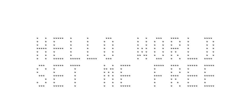
Suppose instead of stripes or checkerboards, we want to
display text. We can represent fairly decent looking individual
characters with an 8x8 grid. We will
divide our 128x128 grid into 8x8 character grids and put up a 16x16 array of
characters. Our 128x128 video grid requires 14 address
bits. Six of these bits are used to
address the 8x8 character grid (HA[2:0] and vCnt[3:1]) this leaves eight bits (HA[6:3] and vCnt[7:4]) for a
function that will select a character for each cell of our 16x16 array of
characters.
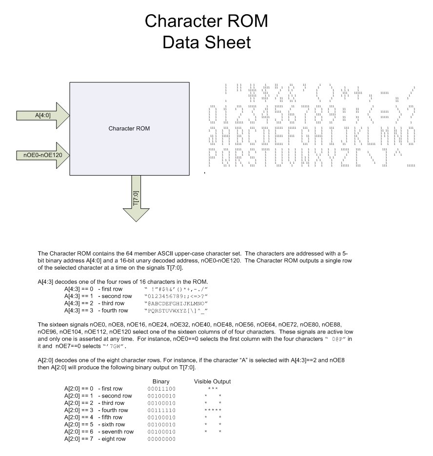
This is a data
sheet (a library for the character ROM is here: /uusoc/facility/cad_common/local/Cadence/lib/charRom
you can add it to your library with the
library editor) for a character ROM containing 4 rows of 16 columns of
characters (64 characters total) each stored as an 8x8 binary array. The 64 characters of the ROM are selected
with six bits (two that select a character row and four that select a character
column, the four column select bits must be sent through a decoder to create
the sixteen unary column select bits the ROM actually uses).
A device that creates a video text pattern would look
something like this:
The Character Function translates the 16x16 character array
addresses into a six bit Character Bus.
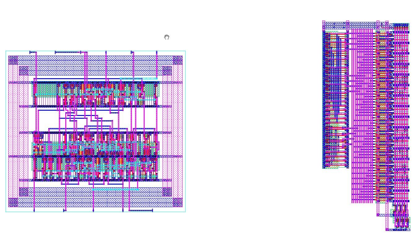
To create a text message, I made both a 5-input ,6-output Verilog
multiplexer and I made another ROM to hold my message
characters. This ROM is configured as 32x6, that
is five address bits and six data outputs.
Here is a comparison
of the layout of these two implementations.
Finally, hook up the vCnt[7:4] bits and the HA[6:3] bits so that the 32 character
message comes out in two rows of characters with 16 characters in each
row. You will need to put in some logic
to do this and avoid multiple copies of the message. (This logic will use some vCnt bits and hBright and vBright).